NVIDIA Is Following Up on Reports of Melted RTX 4090 16-Pin Power Adapters

I'd not be comfortable buying a 4xxx card until they completely replace the connector, preferably with 3x8pin PCIE connectors. I mean a pcie 8 pin connector is only rated at 150W, but I bet anyone they can handle more power before melting than this supposedly 600W connector.
The PCIe eight-pin connectors are rated at 150W at the card, but from the PSU can handle many times that. Thus we see one eight-pin cable from the PSU feeding a pigtail with two eight-pin PCIe connectors.

The main complaint we're seeing attributed to Nvidia is that they have to stay in PCIe spec - so for a card that could pull up to 600W, that means either four eight-pin PCIe leads, or something else.

Since putting four eight-pin PCIe leads on a card significantly increases the PCB surface area, something they seem to be trying to limit, these new 12- and now 16-pin connectors have been adopted. And it seems that the problem is literally down to the robustness of the connector going to the card.

And IMO, it means that someone just didn't think this through; or they did, but concerns were dismissed in order to hit a launch date or due to costs. Notably, there doesn't seem to be a 1:1 correlation between fried connectors and dead GPUs, but unfortunately for Nvidia, they themselves supplied the adapters with these connectors that are failing. So they're still on the hook.
 
Is nVIDIA forcing partners to use this craple™ ? Can they just say OK, we are going to use regular connectors.

This is a solution in search of a problem, I don't think anyone was bothered by the size of the PCB, especially with how huge the coolers are. I don't even believe they are saving money. I bet the supplied adaptor and connector costs more to manufacture than making the pcb slightly larger to accomodate PCIE connectors.
 
So, speaking technically

In high power applications (and in my industry, that's upwards of 5,000A) - you almost always have to go parallel cables, because getting one conductor to carry that much power is just impractical short of engineered solid buswork.

There are always two things you have to pay particular attention to, if you don't have some sort of active mechanism monitoring current per line:
a) The cables all have to be the same size and type and length -- if there is any difference, cable resistances won't be equal, and the current won't flow equally

b) the connectors all have to be identical, and torqued to the correct torque values -- again, same thing as with cable, if one of them is loose or not the same size or what have you, the resistances won't be equal and the current won't flow equally.

I think it's a no-brainer that what we are seeing is (b) == the failures are all happening at a connection point, it will heat up the most at any point of high resistance. So something is not proper in the connector - it could be a bend putting stress on the connector, causing the pins to not all engage equally. It could be a faulty connector, and the female pins just don't have enough friction to adequately engage. It could be faulty connectors on the card and the male pins aren't big enough (I hear that one often from wives). It could be the connectors aren't getting secured / the click retention mechanism isn't holding them in, and after a few thermal cycles they can wiggle themselves loose. Lots of things it could be.

Now, it would also be possible to adjust that with an active mechanism: you could monitor current per line and dynamically adjust the current to balance current coming through parallel connectors. That said, it wouldn't be cheap - but nothing else about these cards is cheap either, and the only way it can really adjust current is by clamping down on a high current line -- which could result in unintentional power throttling on the GPU -- which I would argue is better than physical damage and at least is a symptom that points you to go look at something to correct it before it fails. But I don't know what kind of size that would add to the card (or PSU, it could be added on that end), let along the expense. Just that it's technically possible.

The better solution - and I know we joked about it - would be positive engagement on a single large gauge cable. It probably doesn't need to be automotive posts with 00 wire, but a healthy #8 or #10 size wire, with some sort of positive capture -- a retaining screw, or a lever nut, or something. Now, that's bigger diameter than most power cables use in a computer, but it wouldn't be much bigger than, say, a SATA cable or an HDMI cable, and one round cable would be easier to route and manage than 3 or 4 separate bundles of cabling.

Something like this (these are test leads, and I can't find a good image of a retaining mechanism, but it gives the idea):
View attachment 1995

That said - almost 0 chance they do this. Because 18 and 20 and 22 gauge is just so pervasive in the computer ecosystem.
They don't want to be made fun of with a cable adapter or otherwise, that has thin communication wires and a pair ( or more) of fat strongly connected wires. Thats all.
 
Is nVIDIA forcing partners to use this craple™ ? Can they just say OK, we are going to use regular connectors.
Board designs are approved by Nvidia, so... almost certainly?

Could be that there wasn't another option given to AIBs. Bigger issue is the connector being mandated and the adapter being supplied by Nvidia. Obviously not using the connector or using a better adapter would have avoided this issue entirely.

This is a solution in search of a problem, I don't think anyone was bothered by the size of the PCB, especially with how huge the coolers are. I don't even believe they are saving money. I bet the supplied adaptor and connector costs more to manufacture than making the pcb slightly larger to accomodate PCIE connectors.
With the size of the cooler, it's hard to imagine that PCB size is a real issue right?

The only real advantage I see to the smaller PCBs is when you toss the aircooler and put a water block on it. Then the GPU can be used in smaller systems etc.
 
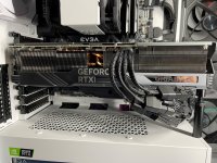
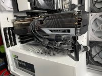
Giving it a go with my 4090 I received today. Haven't tried any games with it yet, but looking to do so soon. I do have a cablemod cable on order to replace this, but for now we'll see how it goes.
4090-1.jpg4090-2.jpg
 

Turns out having the cable angled side to side is the real issue.
 

Turns out having the cable angled side to side is the real issue.
I don't know the guy in the video -- he comes to the right conclusion, but kind of wrong reasoning.

If the cable is getting hot enough to melt the plastic - it's also getting hot enough to melt/soften the solder. So the bending isn't breaking the solder joints or foil to the point where no current is flowing and pushing more current through the other lines... which is what he is claiming.

The solder joint is getting disturbed - but it's still there, still conducting, and still pushing power. But since it's disturbed, it's heating up. Once it gets hot enough -- the plastic melts. and if gets hot enough long enough, the solder joint will ultimately come loose. But once it breaks - there's no longer power going --- the connection is broke.

I should define "disturbed" -- that can mean a lot of different things: the solder joint can crack but still be connected and conducting. The foil underneath can get stressed and crack, but still have electrical connection -- just at a higher resistance. The wire can actually start to break right where the solder wicks up under the insulation -- again, it still is conducting electricity, but you have more resistance, and resistance is what creates the heat.

If the wire were disconnected entirely like he's saying in the video -- the heat would be building up on the middle wires / pins, and the outer cables would be entirely cold - no power through them at all. That's really the only point of contention I take with his video -- the failing joints aren't breaking to the point of disconnection -- but they are obviously getting disturbed. They are just still conducting --- all the way until either the solder joint ultimately melts off entirely or the connector melts to the point it can no longer maintain contact.

Now, his conclusion at the end is that a dedicated wire per pin would fix the problem, and that's why the adapters with the 3090 don't fail. Could be -- it is one less point that can fail. But the wires still have a connection point with the pin - usually crimped - and if you put stress there you can still see failures - just no solder to deal with that may be contributing to this.

*edit*

I still like the automotive battery posts with 00 wire idea better.
 
If wattage rating is not being exceeded by the 4090, then these connector, just never should have had whatever rating they have. A little bend, a little variance in manufacturing should be a completely insignificant issue when it comes to the rating, meaning these things should be over provisioned plenty to account for all manner of issues. IMHO. The rating is wrong, and may have been wrong for a long time, again assuming this card is really not exceeding anything. This means, these ratings are crap, and in truth they have never really been stressed in a meaningful way until now.
 
Last edited:
Become a Patron!
Back
Top