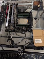
The Z Build(s) 3.0 - Go Big and/or Go Home

I may have found a source at current pricing via the Hardforums. Will update once in my hands.


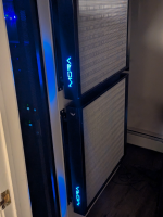
Hehe. His rack is probably a lot nicer than mine. But does he have dual MO-RA 600's? :p
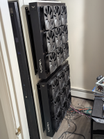
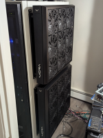
Disassembled the APC rack (I think that was the brand) chillers and pulled the rads from there. It's like 40% jank.
 
Lesson learned.

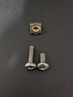
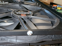
Most rack cage nuts are not 1/4" 28TPI. The cage nut machine screw may fit in a 1/4" 28TPI test thread at Home Depot, but once you order (and wait for) your specialty screws of exactly the length you want, they will not fit in the cage nuts.

Apparently the cage nuts are M6x1.0. Worth noting here. An M6x1.0 screw looks almost exactly the same as a 1/4" 28TPI screw, but has an approximately 0.4mm smaller diameter, so the 1/4" screw just won't go in.

Apparently they are close enough that the M6 screw will thread in a 1/4" 28TPI hole (albeit not as tightly as designed, this should have been my hint) but vice versa just won't work.

Can you tell which is which? 😅

1744913809278.png
 
Last edited:
Can you tell which is which? 😅
After dealing with umpteen bazillion number of cage nuts... and inserts... I can see the thread spacing looks different as well.. but honestly the shorter one because cage nut screws are normally JUST long enough to thread in through a network switch mounting 'ear'.
 
After dealing with umpteen bazillion number of cage nuts... and inserts... I can see the thread spacing looks different as well.. but honestly the shorter one because cage nut screws are normally JUST long enough to thread in through a network switch mounting 'ear'.

It's actually the long one on the left that is M6x1. 😅

The one on the right is the 1/4" 28TPI I special ordered because I needed a shorter screw so it wouldn't protrude too much on the other side and interfere with stuff. :p

No idea why these are so long. I have no idea what they came with. Might have been included with the rack itself, or were a universal set someone ordered at some point. There were a **** ton of them with the rack when I picked it up on craigslist 5 years ago.

Maybe if they were universal ones they made them extra long just to make sure they would fit whatever you needed to mount.
 
Last edited:
Metric vs Standard drives me batty.

I don't really care which one - just pick one and stick with it. Ford used to drive me nuts with this.
 
Metric vs Standard drives me batty.

I don't really care which one - just pick one and stick with it. Ford used to drive me nuts with this.
I'm pretty sure you were the one driving the ford nuts. ;)
 
Metric vs Standard drives me batty.

I don't really care which one - just pick one and stick with it. Ford used to drive me nuts with this.

Honestly, usually this hasn't been a problem for me. But what really threw me off on this one was that I actually brought the screw with me to Home Depot and threaded it into the hole on that fixture they have there in the fastener aisle, it fit, but of course they didn't have 1/4" 28TPI screws, (only 20TPI) so I ordered them online, and they were still the wrong ones 😅
 
So,

Apologies for the extended period of lack of updates.

Between family obligations (travel for my dad's 80th birthday party, bachelor parties, bridal showers, weddings, baby showers, baby "sprinkles", that was a new one for me, mothers day, emergency vet visits, etc.) as well as a lot of casual overtime at work to keep up with a busy preparation for MDR certification, there simply wasn't much time to work on the project.

What little time I did have I spent on actually working on things rather than on documenting them. I intended to post stuff late at night and update with pics, but I was just too **** wiped out.

So this post kicks off some catch-up on that front.

Starting with my realization that I almost made a costly beginner mistake:

01.jpg

The mistake? With the design above I don't have any drain ports low in the loop. It would work well the first time I fill it, and then be an unholy mess to drain it.

I had bought the ball valves I wanted to install for the drain ports, but then I somehow just forgot about them when I started to cut plastic.

The ball valves are going to go between the pump and the inlet at the bottom of each radiator. But that means I need much more space between the pumps and the radiator than with this design. That, and they can't be solid, as I need the space to actually have the outlet there.

So, I went looking for material I could use. The winner became a 1.5" wide and 1" thick 1 foot long ABS bar from McMaster-Carr.

Part of the issue with these pumps is that the ports are very close to the top of the pump top, so if I want any surface to index against, I need to custom shape the bar.

What followed was heavy use of the drill press, bench grinder some drawn blood and a lot of cursing.

ABS has some advantages, but one of the drawbacks is that many tool speeds are too high, and start melting the material which is annoying.

I thought I had taken pictures of all of this, but I can't find them, so I guess I must not have.

Either way, here are the results of the new design:

02.jpg 03.jpg

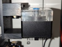
The top block has cut-outs for the Tee-fitting and ball valve for the drain port, as well as a second cutout for the stopper fitting to cap off the secondary unused pump inlet.
 
Last edited:
Then I remembered something else.

Someone I was having a discussion about DDC pumps with reminded me that DDC pumps can have rather short lifespans if they are allowed to run too hot.

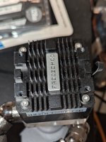
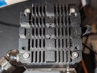
The Freezemod pumps I bought have heatsinks on the bottom, but I decided to add a little more cooling.

01.jpg

The screw holes on the bottom of the heatsink are - however - rectangular rather than square, and don't line up with any common fan sizing.

So, it was time to make another set of brackets...

For better airflow, I was able to pry off the FreezeMod Logo plate:

02.jpg

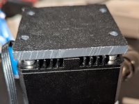
Then I decided to create a flat brackets that cover the entire bottom except for round holes where I will mount the fans

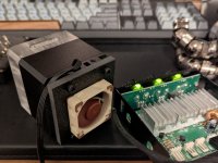
The fans will have to be 40mm. I also don't have a lot of clearance to the next radiator, so I am going to have to go for the narrow 10mm thick fans.

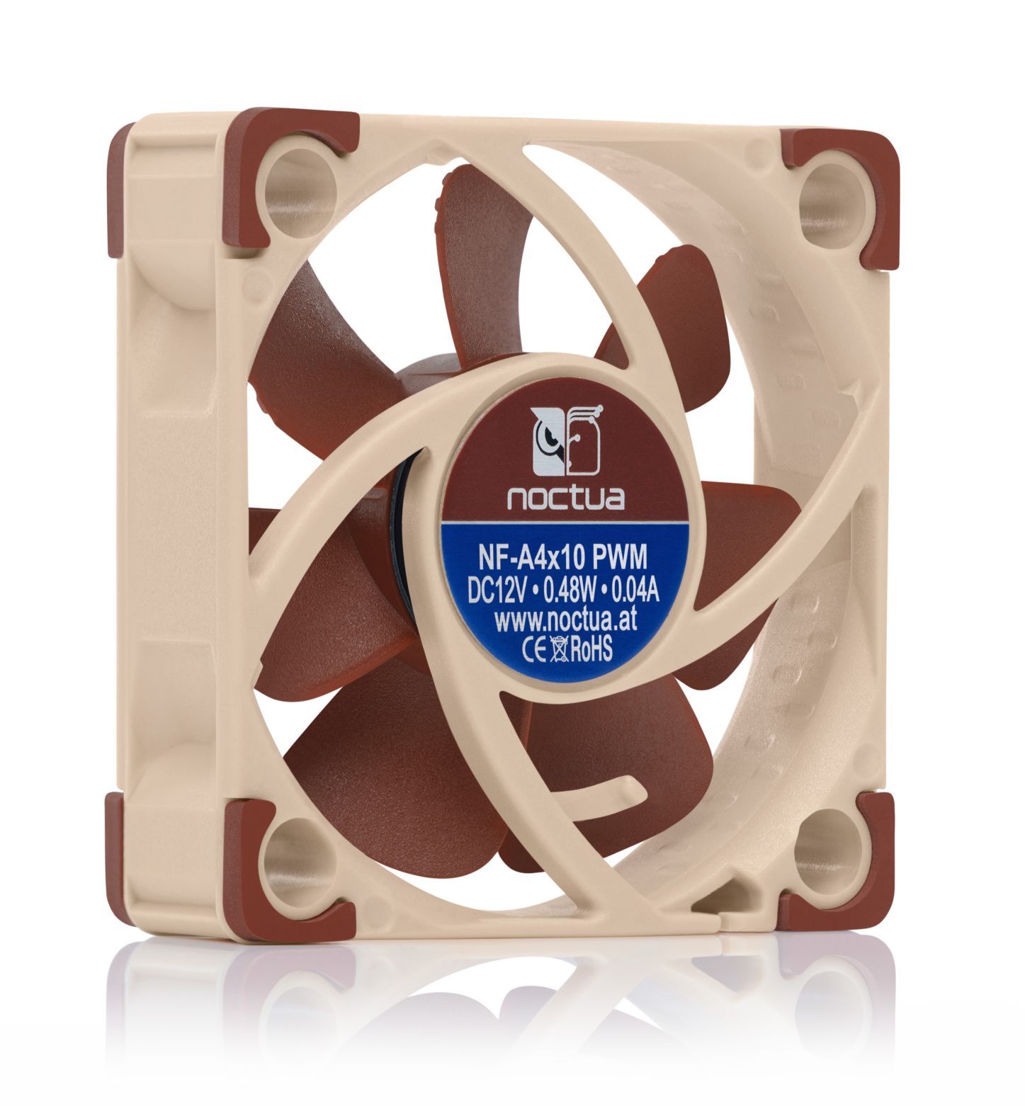
The intent is for the air to be forced through over the fins and exit out the sides. There aren't too many good 40mm fans out there that aren't high rpm Deltas used in enterprise rackmountable enterprise switches or 1U servers, and sound like vacuum cleaners. It will have to be Noctua again. The NF-A4x10 PWM I hope the 1.95 mm H2O static pressure is sufficient to actually press a useful amount of air through there:

03.jpg

My experience has taught me - however - that convection is a pretty weak force, so it doesn't take much in the way of forced air to perform many times better.

04.jpg


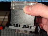
Judging by the finger-tip feel-o-meter, there is a t least a little air coming out the sides of the heatsink gaps at full speed.

At lower speeds, I really cant tell, but there must be something.

I think it works. But ****. The Noctua color scheme is going to bother me

Unfortunately they didn't have the Redux or Chroma series in black available in this size.

I might just have to do something about that.

My builds are usually all about performance. The aesthetics are secondary, but man this is going to bother me too much if I don't.
 
So, this is where things get a little silly.

I looked into options to do away with the Noctua "Napoleon Dynamite" "Tan on Taupe" look.

01.jpg

My first thought was to use automotive vinyl dye, as I have used that on plastics in the past with good results, but some searches revealed less than favorable results. Vinyl dye may be better than paint, but it still - apparently - cakes on the outside and can cause problems.

Then I found this crazy guy on Youtube who used fabric dye for synthetic fibers to dye his fans purple.

Downside? It involves boiling the item to be dyed :ROFLMAO:

He did it. He said it worked for him. I was fully prepared for this to be some sort of prank, but you know what? If I wreck my fans, I can just replace them, so why the hell not?

So we are doing it.

The key is to get the "Synthetic" version, or it does not work.

02.jpg

Unfortunately they do not make a "black" version of the Synthetic dye, only Graphite, but the instructions also say that to achieve a darker color, you can just add more of the dye, and what is black if not a darker graphite?

The instructions also said that to conceal underlying colors you may want to mix in a counter-balancing color. For brown, they recommended using their "Midnight Navy" color mixed in, but that one was out of sock everywhere locally, so I decided to go ahead with just the Graphite.

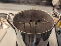
The instructions gave me the proper amount of dye to use based on the weight of the fabric, but I was not dying fabric, and I wanted to get it as dark as possible, so I filled a 3 gallon stock pot up about half way with distilled water (I figured that would work better, but that was not in the instructions), put a drop of dish soap in it as per instructions (presumably to act as a surfactant) and then just dumped the entire bottle in there.

This was many times the required amount of dye per the instructions, but I did want it dark, and I figured I was never going to use the bottle again anyway, so there was no reason to save it for later.

I figured I didn't want the fans to sit on the bottom of the pot or they might melt, so I hung them by the cable from a wire hanger I got from the dry cleaners some time ago...

03.jpg

The instructions say to keep the put with the fabric to be dyed in it at a near boil, stirring occasionally for at least 30 minutes, and to add more time for a darker color. I wanted it dark, and I also presumed that plastic parts might take more time than fabrics, so I left it for an hour.

This second (possibly illegal) kitchen in the finished basement presumably installed by a previous owner of the house as some sort of in-law apartment came in handy.

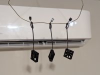
Then the fans came out and I hung them to dry in front of one of the mini-split heat pump heads blowing cool dry air at them for a couple of days.

04.jpg

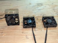
Once dry, the fans looked a little bit like there was excess dye stuck to the outside, so I wiped them down thoroughly with isopropyl alcohol, and they turned out looking great!

05.jpg

Hindsight being 20-20, I probably should have rinsed them off with clean water before drying them, and I wouldn't have had to do this cleaning step, but this worked.

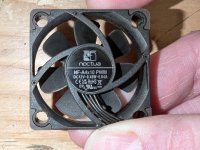
I'm pretty impressed with the results. Everything looks black. Even the rubber vibration pads and the label on the back of the fan turned out nice, which is a bit surprising considering they started out looking like this:

NF-A4x10 PWM


They actually look like they could have come that way, which beat all of my expectations.

07.jpg

The question is, after boiling Noctua fans in black sludgy water for an hour, do they still work?


I've heard that Noctua fans have very good seals around their bearings, which is likely what resulted in this working without gumming up. I wouldn't count on this working with all fans.

06.jpg

Ahh, much better!

So, if you haven't boiled your fans, do you even enthusiast, bro? :D
 
Last edited:
While on the topic of things that are uncharacteristic for me, lets talk about RGB LED lighting.

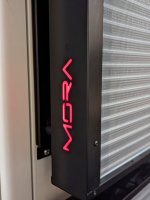
You may all recall that the MORA radiators have these white plastic light diffusers:


I wasn't originally going to do anything with these, but it bothered me that the white plastic diffusers are kind of loose in there, and can fall off. So I felt the need to secure them in place, but then I thought, wouldn't it be nice to have some sort of temperature indicator here, maybe using brightness? And before you know it we went down the slippery slope to colorful disco lighting.

Watercool obviously sells their own proprietary solution that is designed to go in here and interface with their controller, but I am not using Watercools controller. I am using my own Aquaero's, so that complicates things.

At first I was considering just using a standard 12v single color LED light, and hooking it up to a fan output on the Aquaero, and controlling the brightness by adjusting the voltage in fan voltage mode like a traditional voltage fan controller.

It turns out - however - that my Aquaero control units can be hooked up to a Farbwerk RBG controller, and one of those controllers was just two days away courtesy of Amazon Prime, so it was just easier to go that route. So, like RGB lighting or not, it's going to get it. I'll decide later how I use it.

Maybe I have it transition from blue when cold, to red when hot, or something like that? That gives me a quick sanity check as to how things are working by just glancing at it.

Anyway, this was going to require some custom work.

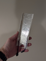
First I bought some white plastic cutting boards to serve as reflectors/diffusers on the inside. I cut and scored folding points in order to create a holder for the LED lighting. And then added some foil tape I had laying around for better reflection.

In my first attempt I added some strips Aquacomputer sells. I knew next to nothing about LED strips and thus decided to just order what they sold, but these strips were very short, and cost a surprising amount. They also did not come with the connectors I needed, so I had to order those separately:

01.png
I also got a bunch of splitters so I could power both sides.
Then when trying to insert it I mashed one of the LED strips and it stopped working. I needed to both adjust the dimensions of the insert, and buy more LED strips. I went with these from Amazon.

For less money than I paid for two short strips from Aquacomputer, I got two entire reels. I didn't need that much, but I figured it couldn't hurt to have extra.

It was a blessing in disguise, as the first attempt was lopsided with different lengths on each side.

Attempt number 2 was much nicer:

02.png

But it turns out it didn't fit either, and mashed the top row of LED's breaking them.


After this, I forgot to take pictures of the final design, but essentially, I removed the top and bottom led rows, and went back to a "one on each side" design. This resulted in less interference, and now everything fit.

I needed to get LED extension cables in order to reach the control box.

It turns out LED connectors are pretty wimpy, and don't hold together well, so I had to use some tape and zip ties to make sure connectors didn't come loose:

03.png 04.png


Anyway, it seems to have worked out quite nicely:

05.png 06.png
 
And then it was time to mount the fan brackets and covers.

The whole 3x3 bracket is designed with two prongs on the bottom (which are just screws with a nylon washer underneath), that stick into matching holes on the radiator, and then it is just supposed to snap in place at the top:

01.png

...but neither of mine did.

It turns out there were some tolerance issues. In my radiators, the bracket sits too low, so the spring loaded ball catches on top don't catch.

Easy solution though. Unscrew the screws at the bottom, stick in a couple more washers and that tightens it up and it works. Doesn't look bad either.

02.png

Aren't 18x 200mm fans a gorgeous sight? :D

03.png

The covers went on much easier. They used the same push-pin style screws as the pump bracket earlier in the thread.

Just remove existing case screws, replace them with pushpin screws, and pop the covers right on, and the spring-loaded catch on the cover does its thing.

With a standard thickness fan, they are snug. They come with spacers though, if you use extra thick fans.


So we are getting pretty close to mounting the reservoirs and pumps and routing tubing.

The next step will be to rewire the pumps so they work on only a 4 pin connector from my Aquaeros, and then we should be off to the races.

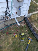
Right now, I am being slightly slowed down - however - as my better half went out and bought a battery electric vehicle, so now I have a side quest that involves installing a level 2 EVSE charger.

This past weekend I got started on making holes and installing conduit...

04.png

Fun times.
 
It turns out LED connectors are pretty wimpy, and don't hold together well
I think they flat out suck. Nice job on the zip ties/tape. I seriously could not believe the type connector manufacturers use for PC LED stuff the first time I got an AIO with them. Some of the ones I've used come with covers that'll snap in place to hold them together but still, ridiculous.
 
I was referring to the AnandTech converts. (Spell correction keeps changing that.. blah)

Ahh.

I was thinking about AT Power supplies or something. Couldn't quite figure out what you were on about. Thanks for clarifying.

You know it is funny. I read Anandtechs articles all the time over the years. Or at least up until 2014 when Anand himself left for Apple and their reviews slowly went to ****.

The funny part is that while I was a reader of Anandtech for almost 20 years, I never once participated in their forums.

I'm honestly not even sure I ever realized that they had forums 😅
 
Or at least up until 2014
Yeah that's about when the site changed trajectory and started going downhill over the next decade.

The funny part is that while I was a reader of Anandtech for almost 20 years, I never once participated in their forums.
Hahahaha same! And on [H] I was a lurker for like 7 years before I finally joined the forums in 2007.
 
I just realized I forgot to update work on the electrical control box.

First I bought a Delta dual volt (12v/5v) power supply from Mouser.

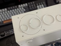
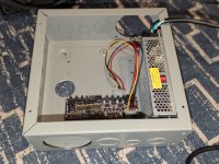
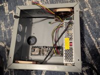
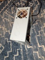
I bought a large-is (10"x10"x4") electrical junction box to use as a control box for the fans and pumps.

The intent was for this box to house the power supply, two Aquacomputer Aquaero 6 LT controllers a small USB hub and a Farbwerk LED controller (Aquabus version) for the LED's.

The reason for selecting the Aquaero 6's are twofold. Firstly, I already have three of them (two of which are in my current build) and I have come to quite like them. Secondly, since this water loop is going to be cooling two PC's (and maybe even more later) and I can't predict when one or the other will be on, I wanted something that could manage the loop independently of the PC's, so I can turn them on or off at will, and have the loop continue to function. And that's the beauty of the Aquaero. You plug sensors into it, and program its profiles, and it takes care of itself. No need for it to communicate with the PC at all. (You can hook it up via USB and have pretty charts and graphs, and have it read system sensors if you want too, but I won't really be doing that. Well maybe the pretty charts and graphs/.

IN working on the box, I remembered something I had forgotten. The Aquaero can be re-flashed with a dedicated firmware that turns it into a slave-device, that adds additional fan/pump channels to the master Aquaero. I decided to change my plans to do this, because that way only the Master ever needs USB connectivity, and the need for the USB hub goes away.

Even so, between the power supply and the aquaeros, there will be some generation of heat inside the box, so it will need some cooling too.

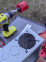
So it was time to make holes:

Electric 01.jpg

Electric 02.jpg


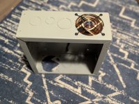
The holes did not wind up being 100% clean, so I decided I was going to come back, sand them, and give them a coat of paint so they didn't look too terrible.

But first I wanted to test fit the fan:

Electric 03.jpg

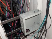
Oh, and I would need to drill mounting holes in the C channel bars I mounted to the back of the rack as well, so I figured I'd get all of the metal work out of the way before painting.

I decided to drill the holes with my trusty DTAP kit, so I wound up with threaded holes directly in the bar stock and didn't have to use any nuts.

Electric 04.jpg

These Greenlee DTAP kits (I got one metric and one SAE) have been very useful!

I also remembered I'd need some mounting holes for the power supply, the Aquaero's and the Farbwerk, as well as a pass-through hole in the back for wires to go to the PC's, so I needed to drill and test fit those too before painting:

Electric 05.jpg

I then tried desperately to find a good paint that would match the general color of the thing. Some Googling suggested that Rustoleum's "Industrial Choice" in grey was a good match, but it proved pretty difficult to find. I wound up special ordering it from Granger, and picking it up at their local store.

When I got it, I guess I found out why. It is labeled for "Industrial or Professional Use Only". Whoops.

Well, I am a "professional". Maybe not the type of professional they had in mind, but....

And I am definitely not a professional painter. I absolutely suck at it:

Electric 06.jpg

Electric 07.jpg

It wasn't as good of a match as suggested, so I wound up having to paint the whole thing, just to cover the exposed metal from my cuts.

There is pretty bad orange peel throughout, but I am going to live with it.

I also had to paint the lid or it wouldn't match, and when doing that, some crap blew in the wind and landed on it, I tried to quickly remove it but it was too late. I am going to have to re-sand it and try again.

And this is where I had to stop, because the other Aquaero I need is still in my current workstation, which has provided a bit of a dilemma that has been slowing me down. There are also other things in the loop on that machine I need in the new loop, like the reservoir, some flowmeters, temperature sensors, etc.

You see, once I break into that workstation, it is down until phase one of the project is complete, and I use that thing for work, so I can't have it down during the week.

This fact has made me hesitate when working on the project some weekends. Would I really have enough time to finish it? This has wound up being a large contributor to the fact that this project has been making such slow progress lately.

I thought I might do it with the extra day over labor day weekend, but I wound up having some other things to do that took my time, and it wasn't in the cards.

But I think I have a solution for that. In my next post.
 
Last edited:
So, my solution for the "weekends are not long enough and I don't want to be stuck without a work machine on Monday" problem is relatively simple in retrospect.

I just need another CPU cooler. Something I can use in my workstation temporarily, allowing me to break down the water loop and take the parts and the time I need to get it done right.

The problem? The Threadripper 3xxxx series used a one generation socket, and that was 6 years ago now. There weren't many cooler out there for it to begin with, and many fewer of them are still around today.

Before starting I read some reviews from back then. I know it is only going to be temporary, but I need it to work OK, and I may even wind up using it in the future when either this Threadripper (or the Milan Epyc in my server) gets moved downstream to secondary workstation duty, and I need a different cooler. SO I didn't want to just get some crap.

My first choice was going to be the Be Quiet! Dark Rock Pro TR4. It is still mentioned on Be Quiet's webpage, but this thing is unobtainable. No one has it, and I can't even find it used, except from one guy in Poland on eBay.

So yeah, that's not happening.

My second choice was going to be the Noctua NH-U14S TR4-SP3.

To my surprise, this one can still be had, and was one click away on Amazon. Because I have read how it is difficult to tame Threadrippers without water cooling, I decided to go for a second NF-A15 PWM fan just to get the most out of the cooler. Luckily Noctua plans for people doing this, and include fan mounting clips for a second fan with the heat sink.

It's not cheap at $109.95, but if it means the difference between making progress on the project and having the whole thing grind to a halt, it's what has to be done.

Unfortunately when it arrived there were signs that it had been opened. The bracket had been removed from the bottom and rotated in the wrong orientation, and there were fingerprints on the otherwise shiny cold plate.

Normally this would piss me of and have me initiating a return and replace, but then I'd have to sit around waiting for another cooler to arrive, and miss the opportunity to make progress for yet another week, so I cleaned it off, re-oriented the mounting bracket, and prepared to install it.

My original plan had been to just install the cooler in my existing case, and start pulling water cooling parts out of it, but the more I thought about it I didn't like this plan. There'd be potential dripping, and maybe I'd forget some part I needed and have to break into it again, etc. etc. So instead I just decided to do the transplant into the rack-mountable case now, and temporarily cool it with the Noctua cooler there, until the water loop is ready.

I knew this meant I probably wouldn't be able to close the 4U case because the Noctua cooler would be too tall, but it's not a big deal. It's temporary!

So I got started on moving all of the parts over to the Sliger rack-mountable case.

Can you believe that? 9 months and 139 posts in, and this build project actually starts doing some PC building 😅

wsrack01.jpg

One thing I failed to consider prior to starting this project is that with 4U server cases, there is rarely any extra space. Things need to be crammed together to make sure everything fits within the 4 rack units. So when building a desktop system, there is usually space to route wires cleanly behind the motherboard.

There is no such space in a 4U rack-mountable case.

So wire management becomes a little tricky.
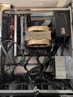
wsrack02.jpg

Sliger were kind enough to provide this bar across the case between the fans and the motherboard though. I'm not sure what it was really intended for (and last I checked they still don't have manuals for any of their cases) but it has lots of holes through it, so it seems like a perfect place to zip tie wires:
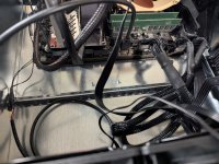
wsrack03.jpg

So I started my wire management.

I'm a little rusty at this, having not done good wire management in a long time, especially in a place where it would all be visible (unlike the good old "shove everything behind the motherboard tray, and mash the rear cover closed whether it wants to or not" approach. 😅)

It was never going to be perfect, but many little zip ties, and a lot of cursing due to my large hands not fitting where I needed them to fit, I think I did OK.
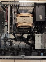
wsrack04.jpg

And yes, I was right about the cooler not fitting 😅

wsrack05.jpg

But as previously mentioned, that is only temporary.


I did have some unanticipated issues though.

If you recall from many posts back, I decided to go with some badass server case fans, the Silverstone FHS 120x.

These are loud and powerful 4,000 rpm screamers producing gobs of both airflow and static pressure, but at low speeds they are actually quite livable, I figured it would be good to have a lot of spare fan capacity just in case I needed it, but anticipated running them at low speeds most of the time.
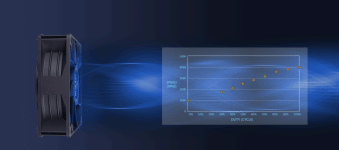
fhs120x-3.gif

Silverstone's design of this fan is actually quite cool, in that they allow you to use the entire PWM duty cycle range to get the speed you want. 100% duty cycle may be a deafening 4,000 freaking rpm, but at 0% duty cycle, they sit at a rather civil 1,000rpm. At 35%-40% duty cycle they make some noise, but really not any more than any other high performance desktop fan does at around 2000rpm.

My plan was to stay in the 0% to 30% range most of the time, and only allow them to kick in to high gear if things were getting unusually hot.

But then Asus had a problem with that. 🤦‍♂️

Asus Q-Fan control is pretty nice, but the problem is Asus thinks that you - their customer - is an idiot, and they have decided to limit how low of a duty cycle range you can configure for your fans.

Yes, if you use Q-Fan tuning you can unlock lower duty cycles than are available out of the box, but it would seem like there are also hardcoded minimums that cannot be changed no matter what.

CPU_FAN and CPU_OPT: These seem to never be allowed to be set below 18% duty cycle no matter what.
CHA_FAN1 and CHA_FAN2: These seem to never be allowed to be set below 26% duty cycle no matter what.
W_PUMP1 and W_PUMP2: The Q-Fan Optimizer doesn't even test these, and they seem to never be allowed to be set below 20% duty cycle no matter what.

Well, I don't want them to scale with the CPU, so the best I could do was connect them to one of the pump headers. At 20% they are sitting at like 1,850 rpm, and that is much higher than I had hoped.

With the door closed, I can't hear them from my office, but I still don't like the fact that they are constantly running at this high speed.

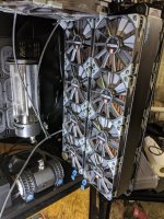
I'll have to see if I can live with it. Otherwise I'll just swap in some of my old 120mm Noctua industrial fans. The good lord knows I have enough of those in my current build, that will soon be "unemployed".
wsrack06.jpg

...but it will be a shame to have these awesome Silverstone fans go to waste.


As for the Noctua cooler? I installed it as instructed with the included Noctua paste, and using the dot pattern recommended in their manual. (a 3x3 and 2x2 pattern interposed on each other for a total 13 dots of thermal paste). Once I was up and running, I decided to do a quick test to see how it held up.

I ran mprime (the Linux version of Prime95) maxing out all 48 threads with small FFT's which they claim is worst case for heat.

The Threadripper is rated at a max temp of 80°C. Once I started the stress test, the CPU temp immediately shot up to 68°C, and then kept slowly rising up to ~78°C. I forgot to check the CPU clocks, but I wouldn't be surprised if it was throttling, or at the very least not achieving its best turbo clocks.

It's good to know that it works, but I probably would not want to daily a Threadripper with this cooler.

But again. It is temporary.
 
Become a Patron!
Back
Top